
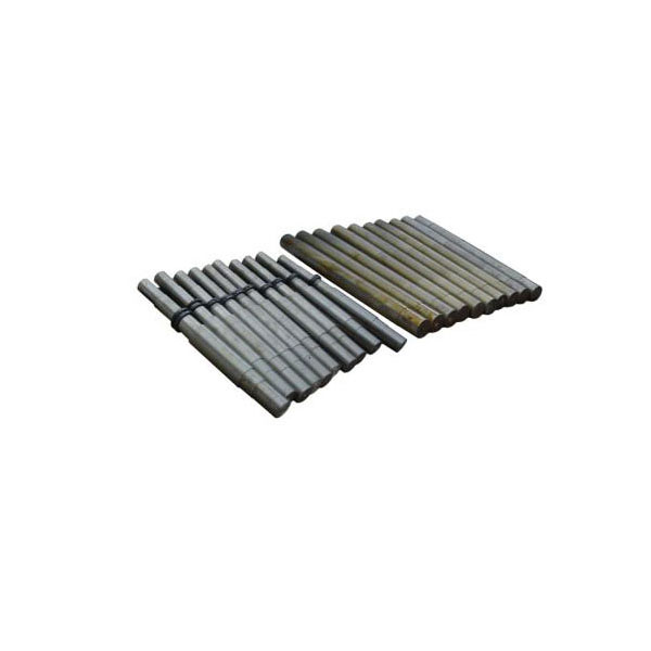
Hammer Shaft / Rotor Shaft
Crusher Main Shaft Assembly — Hammer Crusher Shaft / Impact Crusher Rotor Shaft / VSI Main Shaft — 42CrMo / 40CrNiMo / 34CrNiMo6 / 4140 / 4340
Hammer Shaft / Rotor Shaft / Crusher Rotor Shaft
Material Specifications & Selection Guide
| Grade | Material | Tensile (MPa) | Yield (MPa) | Hardness (HB) | Application |
|---|---|---|---|---|---|
| 45# | Carbon Steel | 600 | 355 | 170-210 | Small crushers (PC400-PC600) |
| 40Cr | Alloy Steel (Cr-Mo) | 980 | 785 | 240-300 QT | Standard duty, medium crushers |
| 42CrMo | Alloy Steel (Cr-Mo) | 1080 | 930 | 280-340 QT | Heavy impact, PCK800-PCK1000 |
| 34CrNiMo6 | Ni-Cr-Mo Alloy | 1100-1300 | 900-1050 | 310-370 QT | Metal shredders, max. shock load |
| 40CrNiMoA | Ni-Cr-Mo Alloy | 1100 | 950 | 300-360 QT | Extra-large PCK1200+, shredders |
| Shaft Type | Shaft Dia. (mm) | Length (mm) | Bearing Seat (mm) | Keyway (mm) | Runout Tolerance |
|---|---|---|---|---|---|
| Small (PC400-PC600) | 60-90 | 800-1400 | 60-90 k6/h7 | 18-25 | 0.02 mm |
| Medium (PC800-PCK800) | 90-140 | 1400-2200 | 90-140 m6/h7 | 25-36 | 0.03 mm |
| Large (PCK1000-PCH1010) | 140-200 | 2200-3200 | 140-200 m6/h7 | 36-50 | 0.04 mm |
| Extra-Large (PCK1200+) | 200-280 | 3200-4500 | 200-280 m6/h7 | 50-70 | 0.05 mm |
| Shredder Main Shaft | 250-400 | 3500-5500 | 250-400 n6/h6 | 60-100 | 0.05 mm |
| Crusher Model | Rotor Dia. x Width | Shaft Dia. (mm) | Bearing Type | Rec. Material | OEM Ref. |
|---|---|---|---|---|---|
| PC400x300 | 400×300 | 60-70 | Self-aligning 222xx | 45# / 40Cr | SBM / Liming |
| PC600x400 | 600×400 | 70-85 | Self-aligning 222xx | 40Cr | SBM / Sanyyo |
| PC800x600 | 800×600 | 90-110 | Spherical 223xx | 40Cr / 42CrMo | SBM PC800 |
| PCK1000x800 | 1000×800 | 130-160 | Spherical 232xx | 42CrMo | FLSmidth EV / Hazemag |
| PCH1010 / PCK1200 | 1000-1200 | 160-200 | Spherical 232xx | 42CrMo / 34CrNiMo6 | Liming PCH / Sinoma |
| Metal Shredder | 1200-2000 | 250-400 | Spherical 240xx | 34CrNiMo6 / 40CrNiMoA | Metso Lindemann / Texas |
Selection Quick Reference
- Small hammer crushers (PC400-PC600, up to 30 t/h): 45# carbon steel shafts (60-85 mm dia.) with normalised condition — cost-effective for low-load applications where shaft replacement is simple and downtime acceptable. Surface hardness 170-210 HB with good machinability. Upgrade to 40Cr (240-300 HB QT) for 1.5-2x fatigue life at 20-30% cost premium
- Medium crushers (PC800-PCK800, 30-80 t/h): 40Cr or 42CrMo quench-tempered (QT) alloy steel shafts (90-140 mm dia.) — 42CrMo preferred for its higher tempering resistance (up to 500 C without softening) and better hardenability in larger sections. Bearing seats induction-hardened to 48-55 HRC for 2-3 mm depth to resist fretting
- Large crushers (PCK1000-PCH1616, 80-300 t/h): 42CrMo or 34CrNiMo6 shafts (140-200 mm dia.) — nickel addition in 34CrNiMo6 dramatically improves through-hardenability for large sections (>150 mm) and low-temperature toughness (down to -40 C). Bearing seats ground to Ra 0.4-0.8 um and cylindrical tolerance IT6 for precision bearing fit
- Metal shredders (extreme shock, 40-100 t/h): 34CrNiMo6 or 40CrNiMoA shafts (250-400 mm dia.) — the 1.4-1.7% Ni + 0.15-0.3% Mo combination delivers 1,100-1,300 MPa tensile with exceptional impact toughness (KV >40 J at -20 C). These shafts absorb repeated shock from tramp metal without fatigue crack initiation. Ultrasonic testing (UT) per ASTM A388 Level II mandatory for every shaft
- Custom OEM service: Reverse-engineer from your worn shaft or OEM drawing. ZHILI reproduces exact bearing seats, keyway dimensions (JS9/P9 tolerance), rotor disc fit, and shaft-end geometry. Full UT, dye penetrant, and dimensional inspection report supplied with every shaft. Delivery 15-20 days for standard grades, 25-30 days for 34CrNiMo6/40CrNiMoA large forgings
Certifications & Authorizations
Quality you can verify. Partners you can trust.
Custom OEM / ODM
From drawing to delivery — one-stop customization, no minimum order
Send Drawing
Upload your technical drawing (PDF, DWG, STEP, IGES) or share sample photos with dimensions
Engineering Review
Material recommendation, casting process design, DFM analysis — free quotation within 24 hours
Sampling & Test
Prototype production with full inspection: hardness test, spectrometer, dimensional check
Production & Ship
ISO 9001 certified. 15-25 days standard lead time. Global shipping with full documentation
Frequently Asked Questions
Quick answers to common questions about our crusher rotor shafts & hammer shafts
Rotor shaft material selection is a fatigue life decision. The shaft experiences fully reversed bending stress from rotor weight plus torsional shock every time a hammer strikes — typically 5-15 million cycles per year. Material choice must prioritise fatigue resistance:
- 45# carbon steel (entry level, small crushers only): Appropriate for PC400-PC600 crushers where shaft diameter <90 mm and replacement is quick. Tensile 600 MPa, yield 355 MPa. The fatigue limit of 45# (approximately 270 MPa for smooth specimens) provides adequate life at these loads, but the low hardenability means induction-hardened bearing seats may not achieve uniform case depth in sections >70 mm. Use 40Cr instead for any shaft >80 mm diameter — the cost difference ($100-200 per shaft) is negligible relative to the downtime cost of a 45# shaft fatigue failure.
- 40Cr / 42CrMo quench-tempered alloy steel (standard for 80% of applications): 40Cr (980 MPa tensile, 785 MPa yield) provides the best cost-performance ratio for shafts 60-110 mm diameter. The chromium addition (0.8-1.1%) improves through-hardenability — the entire cross-section achieves uniform mechanical properties after QT, not just the surface. 42CrMo (1,080 MPa tensile, 930 MPa yield) adds 0.15-0.25% Mo for improved temper resistance and hot strength. Upgrade from 40Cr to 42CrMo when: (a) shaft diameter exceeds 110 mm (40Cr hardenability limit); (b) crusher runs hot (>80 C at bearings, softening 40Cr temper); (c) hammer impact force exceeds 50 kN.
- 34CrNiMo6 / 40CrNiMoA nickel-chromium-molybdenum (premium, large shafts only): The 1.4-1.7% nickel dramatically improves through-hardenability for sections >150 mm — 34CrNiMo6 achieves uniform properties in shafts up to 500 mm diameter, where 42CrMo would have a soft core. Nickel also improves low-temperature impact toughness (KV >40 J at -40 C) — critical for crushers operating outdoors in cold climates where brittle fracture risk increases. The fatigue limit of 34CrNiMo6 is approximately 520 MPa — roughly 1.7x higher than 42CrMo (310 MPa). This directly translates to 3-5x longer fatigue life. Use 34CrNiMo6 when: (a) shaft diameter >150 mm; (b) previous shafts failed due to fatigue (beach marks visible on fracture surface); (c) crusher runs 24/7 and downtime costs >$5,000/hour.
- Cost decision: A 34CrNiMo6 shaft costs approximately 2.5-3x more than 42CrMo for the same dimensions (higher raw material cost + longer forging/machining time + mandatory UT inspection). The payback calculation: if 42CrMo shaft lasts 3 years on your crusher, 34CrNiMo6 will last 8-12 years — a one-time upgrade eliminates one or two shaft replacements and the associated 5-10 day shutdowns. The larger the shaft and the higher the downtime cost, the stronger the case for nickel alloy.
Quick rule: Shaft diameter <100 mm → 40Cr (best value). Shaft 100-150 mm → 42CrMo (hardenability + temper resistance). Shaft >150 mm or previous fatigue failure → 34CrNiMo6 (through-hardness + fatigue life). Metal shredder → always 34CrNiMo6 or 40CrNiMoA (tramp metal shock means zero margin for material compromise).
Rotor shaft failure is the most expensive single-point failure in a hammer crusher. A broken shaft destroys the rotor assembly, housing, bearings, and often the foundation. Most failures give clear warning signs months before the event:
- Fatigue fracture (most catastrophic, #1 cause of shaft replacement): Initiated by a microscopic crack at a stress concentration — typically at the bearing shoulder radius, keyway corner, or a machining mark. The crack propagates with each rotation (reversed bending) creating characteristic “beach marks” visible on the fracture surface. Total cycles to failure: 2-20 million typically. Early detection: (a) ultrasonic testing (UT) of shaft at bearing shoulders every 5,000 operating hours — any indication >2 mm requires monitoring; (b) vibration monitoring — a step increase in 1x running speed vibration amplitude (shaft bow or crack opening under load) is the earliest external sign; (c) sudden increase in bearing temperature — a growing crack changes the shaft stiffness, altering bearing loading. Prevention: generous fillet radii at all diameter changes (R >0.1x shaft diameter minimum, R >0.15x recommended), polished surface finish (Ra <0.8 um) at all fillets, and shot peening of the fillet zone to induce compressive residual stress.
- Bearing seat wear (fretting, most common progressive damage): The inner race of a spherical roller bearing is interference-fitted (m6 or n6) on the shaft. Under load, microscopic relative motion between the inner race and shaft creates fretting corrosion — a red-brown iron oxide powder (cocoa powder appearance). This powder is abrasive and accelerates wear, eventually loosening the fit to a clearance condition. Once clearance exists, the inner race rotates on the shaft, wearing a groove and destroying the shaft. Detection: (a) inspect for red-brown powder at bearing inner race edges every 1,000 hours; (b) use feeler gauge between inner race and shaft shoulder — any gap >0.05 mm indicates the fit is loosening; (c) vibration analysis — a loosened bearing fit generates 3x-5x running speed harmonics. Repair: if wear depth <0.1 mm, sleeve the shaft with a thin-walled hardened steel sleeve (Loctite 638 bonded); if >0.1 mm, metal-spray or weld-build up and re-machine to original dimension.
- Keyway wallowing (progressive torsional damage): Each hammer impact generates a torsional shock that loads and unloads the keyway. Over millions of cycles, the keyway edges deform plastically, widening the keyway. A 25 mm keyway becomes 26 mm, then 28 mm, then the key shears — and if the rotor disc spins freely on the shaft, the resulting imbalance destroys the crusher. Detection: measure keyway width at 3 positions with a calibrated feeler gauge or internal micrometer every 2,000 hours. Increase >0.15 mm requires key replacement with oversize key; increase >0.50 mm requires machining to next standard oversize or shaft replacement. Prevention: use a tight-fit key (P9/h9 tolerance) — never a loose sliding fit key that rocks under load; radius the key corners to match the keyway fillet; apply anti-seize in the keyway to reduce fretting but NOT on the side faces (which transmit torque).
UT inspection schedule: At every major shutdown (6-12 months), perform ultrasonic testing of the shaft at: (1) both bearing shoulder fillets — most common fatigue initiation sites; (2) keyway ends — second most common; (3) any diameter change or groove. Record all indications with size, location, and depth. If an indication grows between inspections (depth increased by >20%), plan shaft replacement at the next scheduled shutdown — do not wait until the next inspection. A growing fatigue crack means the shaft is in the propagation phase, and failure could occur within weeks.
A rotor shaft assembly weighing 2-15 tons spinning at 600-1,000 RPM has zero tolerance for installation error. Bearing life is inversely proportional to the cube of misalignment — 0.10 mm misalignment reduces bearing life by approximately 50%:
- Shaft preparation and bearing mounting (step 1 — critical): Measure shaft bearing seats with a micrometer at 3 axial positions and 4 radial positions (12 measurements per seat) to verify roundness (tolerance IT6 = 0.016 mm for 100 mm diameter) and taper (<0.005 mm). Heat bearings to 110-120 C using an induction heater (never an oil bath — oil contamination in the bearing reduces life). Slide the heated bearing onto the shaft in one continuous motion — the interference fit of 0.02-0.05 mm (m6/H7 for 100 mm shaft) grips within 10-15 seconds as the inner race cools. Do NOT use a hammer or drift on any bearing component. After cooling, verify the bearing is fully seated against the shaft shoulder — any residual gap >0.03 mm means the bearing will creep under load.
- Rotor assembly and static balancing (step 2): Assemble rotor discs, spacers, and hammer shafts on the main shaft. Tighten all rotor disc clamping bolts in a cross-pattern star sequence to 50% torque, then 100% torque. Static-balance the assembled rotor (without hammers) on knife-edge balancing rails — permissible residual unbalance Uper = G x 9.55 x rotor_mass / RPM (G=6.3 for G6.3 grade). For a 5,000 kg rotor at 800 RPM: Uper = 6.3 x 9.55 x 5,000 / 800 = 376 g-mm/kg, so total permissible residual = 1,880 g-mm. Add or remove balance weight at the rotor disc periphery. Install hammers, re-check balance — hammer weight variation must be within ±0.5% across the set.
- Housing alignment and shaft installation (step 3): The two bearing housings must be aligned in both horizontal and vertical planes. Use a precision machinist level (0.02 mm/m sensitivity) on the shaft journal. Maximum permissible angular misalignment between bearings: 0.05 mm per 100 mm of bearing spacing (0.0005 rad). Use dial indicators on the shaft ends — lift and rotate the shaft by hand, measuring runout at both bearing positions. Any binding or tight spot during manual rotation indicates bearing or housing misalignment — do not run the motor until the shaft rotates freely with <5 Nm of torque (approximately 5 kg force on a 1 m lever).
- Run-in procedure (step 4 — do not skip): Start the crusher empty and run at 10-20% speed for 30 minutes. Monitor bearing temperature every 5 minutes — if temperature rises >2 C/min, stop and investigate. Increase to 50% speed for 30 minutes, then 75% for 30 minutes, then 100%. During the entire run-in (2-3 hours), vibration measured at each bearing housing must remain below 4.5 mm/s RMS (ISO 10816-3, Zone A). After run-in, feed material gradually — 25% design rate for 1 hour, 50% for 1 hour, 75% for 1 hour, then full rate. This progressive loading beds the bearings and rotor discs without thermal shock. Re-torque all rotor disc bolts after 8 hours of full-load operation.
Critical safety note: A rotor assembly stores enormous kinetic energy — a 5,000 kg rotor at 800 RPM stores approximately 4.4 MJ (equivalent to 1 kg of TNT). Never stand in the plane of rotation. Test the crusher with remote vibration monitoring for the first 8 hours after any shaft or bearing change. If vibration exceeds 7.1 mm/s RMS (ISO Zone B), stop immediately. ZHILI supplies fully assembled and balanced rotor assemblies with OEM-compatible shafts — delivered ready-to-install with certified UT and dynamic balance reports. This eliminates the three highest-risk installation steps and reduces commissioning time from 3-5 days to 1 day.
Related Products
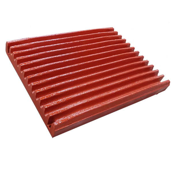
Jaw Plate
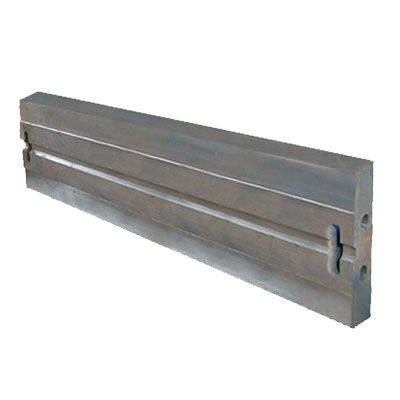
Blow Bar
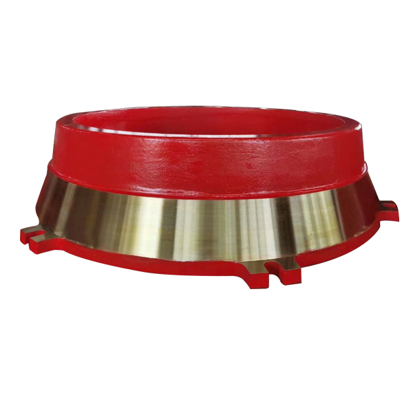
Mantle & Concave
Grate Bar
Contact Us
Get a quote within 24 hours. Send us your inquiry today.

+86 199 8785 7268
Mon-Sat 8AM-10PM CST Scan to chat — English, Spanish, Chinese Send photos of worn parts for instant quote

+86 199 8785 7268
Scan to follow — factory updates and quotes Chat in Chinese or English