
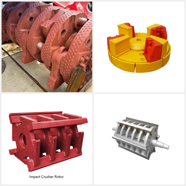
Crusher Rotor
VSI / HSI Impact Crusher Rotor Assembly — Rotor Body / Rotor Tip / Distributor Plate / Feed Eye Ring / Back-Up Tip — Alloy Steel / High Manganese Steel / Tungsten Carbide Insert
Crusher Rotor / Hammer Crusher Rotor / Impact Crusher Rotor
Material Specifications & Selection Guide
| Grade | Material | Tensile (MPa) | Yield (MPa) | Hardness (HB) | Application |
|---|---|---|---|---|---|
| ZG270-500 | Cast Carbon Steel | 500 | 270 | 150-190 | Small PC400-PC600, low stress |
| ZG310-570 | Cast Carbon Steel | 570 | 310 | 160-210 | Medium PC800-PCK800, standard |
| ZG35SiMn | Cast Si-Mn Alloy Steel | 690 | 410 | 200-250 QT | Large PCK1000+, high impact |
| ZG42CrMo | Cast Cr-Mo Alloy Steel | 880 | 690 | 240-300 QT | Heavy impact, metal shredders |
| ZG34CrNiMo6 | Cast Ni-Cr-Mo Alloy | 1000-1150 | 800-950 | 280-340 QT | Max. duty, 24/7, tramp metal risk |
| Rotor Type | Rotor Dia. (mm) | Rotor Width (mm) | Hammer Shafts | Weight (kg) | Balance Grade |
|---|---|---|---|---|---|
| Small Hammer (PC400-PC600) | 400-600 | 300-600 | 3-4 rows | 200-600 | G6.3 |
| Medium Hammer (PC800-PCK800) | 800-1000 | 600-1000 | 4-6 rows | 800-2,500 | G6.3 |
| Large Hammer (PCK1000-1200) | 1000-1400 | 1000-1400 | 6-8 rows | 3,000-6,000 | G6.3 |
| Impact Crusher (PF1007-PF1820) | 700-1800 | 700-2000 | 3-4 blow bars | 1,000-8,000 | G6.3 |
| Metal Shredder Rotor | 1200-2000 | 1200-3000 | 8-16 hammers | 5,000-18,000 | G2.5 |
| Crusher Model | Rotor Dia. x Width (mm) | Hammer Rows | Rec. Material | Weight (kg) | OEM Ref. |
|---|---|---|---|---|---|
| PC400x300 | 400×300 | 3 | ZG270-500 | 120-200 | SBM / Liming |
| PC600x400 | 600×400 | 4 | ZG270-500 | 300-500 | SBM / Sanyyo |
| PC800x600 | 800×600 | 4-6 | ZG310-570 | 800-1,200 | SBM PC800 |
| PCK1000x800 | 1000×800 | 6 | ZG35SiMn | 2,000-3,500 | FLSmidth EV / Hazemag |
| PF1010 / PF1210 | 1000×1000 | 4 blow bars | ZG310-570 | 1,200-2,000 | Liming / Sandvik |
| PF1820 / PF2020 | 1800×2000 | 4-6 blow bars | ZG35SiMn / ZG42CrMo | 6,000-10,000 | Metso NP / Sandvik CI |
Selection Quick Reference
- Small hammer crushers (PC400-PC600, up to 30 t/h): ZG270-500 cast carbon steel rotor — cost-effective for low-to-moderate impact loads with rotor weight 120-500 kg. 3-4 hammer rows on hardened hammer shafts. Pre-stress shot peened at disc-to-shaft joints for fatigue resistance. Balance to G6.3 per ISO 1940-1
- Medium hammer crushers (PC800-PCK800, 30-80 t/h): ZG310-570 cast steel — higher tensile (570 MPa) handles the increased centrifugal stress at rotor peripheral speed of 30-40 m/s. 4-6 hammer rows with precision-bored hammer shaft holes (H7 tolerance) to eliminate hammer shaft rocking. Rotor weight 800-2,500 kg
- Large hammer crushers (PCK1000-PCK1200+, 80-300 t/h): ZG35SiMn quench-tempered cast alloy steel — silicon-manganese addition improves through-hardenability for sections >150 mm and fatigue resistance under reversed bending. 690 MPa tensile with 200-250 HB hardness. 6-8 hammer rows, rotor weight 3,000-6,000 kg. Mandatory UT inspection per ASTM A609 Grade II
- Impact crusher rotors (PF1010-PF1820): ZG310-570 or ZG35SiMn with 3-4 blow bar mounting slots. Blow bar seats must be induction-hardened to 45-50 HRC to resist plastic deformation from repeated blow bar impact wedging. Rotor weight 1,000-10,000 kg. Dynamic balancing to G6.3 at operating speed mandatory before shipment
- Metal shredder rotors (extreme duty): ZG42CrMo or ZG34CrNiMo6 cast alloy steel — 880-1,150 MPa tensile with exceptional toughness for tramp metal impact absorption. 8-16 hammer rows on hardened hammer pins (42CrMo, 300-340 HB). Rotor weight 5,000-18,000 kg. Balance grade G2.5 (tighter than G6.3) due to higher operating speed (600-900 RPM). 100% UT + MT (magnetic particle) inspection of all critical sections. ZHILI delivers with full NDT report and dynamic balance certificate
Certifications & Authorizations
Quality you can verify. Partners you can trust.
Custom OEM / ODM
From drawing to delivery — one-stop customization, no minimum order
Send Drawing
Upload your technical drawing (PDF, DWG, STEP, IGES) or share sample photos with dimensions
Engineering Review
Material recommendation, casting process design, DFM analysis — free quotation within 24 hours
Sampling & Test
Prototype production with full inspection: hardness test, spectrometer, dimensional check
Production & Ship
ISO 9001 certified. 15-25 days standard lead time. Global shipping with full documentation
Frequently Asked Questions
Quick answers to common questions about our crusher rotors
Rotor material selection is a fatigue and toughness decision. The rotor experiences fully reversed centrifugal stress (tension-compression cycling at 10-20 Hz) plus impact shock every time a hammer strikes material. Material choice must balance strength, toughness, and cost:
- ZG270-500 (entry level, small rotors only): Adequate for PC400-PC600 crushers with rotor weight under 800 kg. The centrifugal stress at 25-30 m/s peripheral speed generates approximately 20-40 MPa stress at the rotor body — well within the 500 MPa tensile capacity. However, the low yield strength (270 MPa) means minimal reserve against impact overload. Use only when rotor replacement is quick (<4 hours) and downtime cost is low. Upgrade to ZG310-570 for any rotor >800 kg or where impact from uncrushable objects is possible.
- ZG310-570 (standard for 70% of crusher rotors): The benchmark for PC800-PCK1000 rotors weighing 800-3,000 kg. 570 MPa tensile with 310 MPa yield provides a 1.5-2x fatigue life improvement over ZG270 through higher fatigue limit (approximately 250 MPa vs. 200 MPa). The moderate carbon content (0.30-0.40% C) provides good weldability — critical for repair welding of worn hammer shaft bores or disc edges. Normalised condition with optional stress relief after welding.
- ZG35SiMn (silicon-manganese upgrade, for large rotors): The 0.6-0.9% Si + 1.1-1.4% Mn addition dramatically improves through-hardenability for sections >150 mm. After quench-and-temper (QT), ZG35SiMn achieves 690 MPa tensile with 200-250 HB throughout — ZG310-570 would have a soft core in sections this thick. The improved fatigue limit (approximately 310 MPa) extends rotor life 1.5-2x vs. ZG310-570. Use for PCK1000+ rotors (3,000-8,000 kg) where a fatigue failure would destroy the crusher housing. Cost premium 30-50% over ZG310, justified when rotor replacement downtime exceeds 2 days.
- ZG42CrMo / ZG34CrNiMo6 (premium, for metal shredders and extreme duty): Chromium-molybdenum or nickel-chromium-molybdenum cast alloy steel delivers 880-1,150 MPa tensile with exceptional impact toughness (KV >30 J at -20 C). The Mo addition resists temper embrittlement during long-term operation at elevated temperature (rotors run 60-90 C from bearing friction). ZG34CrNiMo6 achieves uniform properties in sections up to 500 mm. Use for: (a) metal shredder rotors processing automotive scrap with tramp metal; (b) crushers in remote locations where a rotor failure means weeks of downtime; (c) any rotor weighing >8,000 kg where the consequences of failure are catastrophic. Cost premium 80-120% over ZG310 — a $50,000 rotor vs. $25,000 — but one prevented failure justifies the cost.
Decision matrix: Rotor weight <800 kg, downtime cost low → ZG270. Rotor 800-3,000 kg, standard duty → ZG310. Rotor 3,000-8,000 kg, high production → ZG35SiMn. Rotor >8,000 kg, metal shredder, or remote location → ZG42CrMo/ZG34CrNiMo6. When in doubt, upgrade one grade — the material cost increase is 20-50% per grade, but the cost of one prevented rotor failure is 10-50x the material premium.
Rotor failure is the most destructive event in crusher operation. A 5,000 kg rotor at 800 RPM stores energy comparable to 1 kg of TNT. Understanding failure modes and early detection saves the entire crusher:
- Disc cracking at hammer shaft bores (most common, #1 fatigue failure): Each hammer impact creates a radial force pulse through the hammer shaft into the disc bore. The bore experiences hoop stress that cycles from near-zero to maximum with each hammer strike — typically 5-15 million cycles per year. Cracks initiate at the bore edge (stress concentration at the sharp corner where the bore meets the disc face) and propagate radially outward. Early detection: (a) dye penetrant inspection of all hammer shaft bores every 1,000 hours — any linear indication >3 mm requires stop-drilling (6-8 mm hole at crack tip) and monitoring; (b) vibration trending — a step increase in broadband vibration at 3x-10x running speed indicates developing disc cracks. Prevention: generous edge radius at bore openings (R3-5 mm minimum), shot peen the bore surface to induce compressive residual stress, and maintain correct hammer shaft fit (H7/g6 sliding fit — too tight stresses the bore, too loose hammers the bore).
- Hammer shaft bore elongation (progressive, accelerates if ignored): When hammer shafts are loose in their bores (clearance >0.10 mm), the shaft rocks under each impact, peening the bore surface. The bore becomes oval — diameter increases 0.5-1.0 mm in the impact direction. This oval bore allows even more shaft movement, creating a self-accelerating failure. Detection: measure all hammer shaft bores with a bore gauge every 2,000 hours — ovality >0.10 mm requires sleeving or re-boring to the next oversize shaft. A 0.5 mm oval bore can become 3 mm within 500 additional hours if uncorrected. Prevention: maintain correct hammer shaft-to-bore clearance (0.03-0.08 mm for hammer shafts <100 mm diameter); replace shafts when diameter wear exceeds 0.10 mm. A $200 hammer shaft that is slightly loose will destroy a $10,000-50,000 rotor disc set.
- Rotor imbalance (most detectable, easiest to correct): Uneven hammer wear creates mass asymmetry. A 1 kg imbalance at 800 mm radius on a 5,000 kg rotor at 800 RPM generates approximately 5,600 N of unbalanced centrifugal force — 11% of rotor weight pulling sideways. This force flexes the main shaft, overloads bearings (reducing life by 50-70%), and creates fatigue stress in the rotor discs. Detection: vibration trending — 1x running speed amplitude is directly proportional to imbalance. If 1x amplitude increases >25% between measurements, re-balance immediately. Every hammer change requires a balance correction — do not assume new hammers of equal weight are balanced; manufacturing tolerances create 0.2-0.5% weight variation which is significant at rotor speeds. Prevention: dynamic balancing after every hammer change; schedule hammer rotation to maintain weight symmetry; record hammer weights in a log and pair hammers by weight for opposite positions.
Inspection schedule: Every 200 hours — vibration check (1x amplitude for imbalance, broadband for cracks). Every 1,000 hours — dye penetrant inspection of hammer shaft bores and disc-to-shaft junctions. Every 2,000 hours — bore gauge measurement of all hammer shaft bores (ovality check). Every major shutdown (6-12 months) — UT inspection of rotor discs for internal defects, especially at bore edges and any previous stop-drilled cracks. Record all measurements and trend over time — the trend tells you when to replace, not the absolute value.
Rotor balancing and installation is the single most important quality step in crusher assembly. A precisely balanced rotor protects bearings, reduces vibration, and extends disc fatigue life 3-5x:
- Dynamic balancing procedure (shop, before shipment): Assemble the complete rotor including main shaft, all discs, spacers, hammer shafts, and hammers. Mount the rotor on a dynamic balancing machine with bearing supports matching the crusher bearing span. Spin at 10-20% of operating speed (typically 80-160 RPM for a 800 RPM rotor) — this is sufficient to measure imbalance because centrifugal force is proportional to speed squared. Measure imbalance magnitude and angular position in two correction planes (typically at the end discs). Add or remove weight at the disc periphery: drilled balance holes (remove weight) or bolt-on balance weights (add weight). Target residual imbalance Uper = G x 9.55 x rotor_mass / RPM. For G6.3, 5,000 kg at 800 RPM: Uper = 6.3 x 9.55 x 5,000 / 800 = 376 g-mm/kg. Total permissible = 376 x 5 = 1,880 g-mm — equivalent to 1.9 grams at 1 metre radius or 19 grams at 100 mm radius.
- Hammer weight matching (critical, must be done before balancing): Weigh every hammer individually on a calibrated scale (±0.1 kg for hammers 20-100 kg). Group hammers into matched pairs with weight difference <0.5% (e.g., 50.0 kg and 50.2 kg = 0.4% difference, acceptable). Install the heaviest pair opposite each other on the rotor, then the next heaviest pair at 90 degrees, and so on. Never install the heaviest and lightest hammers adjacent — this creates a couple imbalance that is harder to correct. Document all hammer weights and positions in a rotor assembly log — this is the reference for future hammer changes and rotation. When replacing worn hammers, the new set must be within ±0.5% of the documented weights from the original balancing.
- Installation and alignment (on-site): Lower the complete balanced rotor assembly into the crusher housing using a crane with at least 1.5x rotor weight capacity. The rotor assembly must be supported at the bearing locations during lifting — never lift by the shaft ends alone (induces bending). Align the bearing housings with a precision machinist level (0.02 mm/m sensitivity) — maximum permissible angular misalignment is 0.05 mm per 100 mm bearing spacing. Install bearings (pre-heated to 110-120 C on inner race) and bolt bearing housings to the crusher frame. Tighten bearing housing bolts to specification and verify alignment has not shifted — a tightened housing can warp the bearing seat by 0.02-0.05 mm, enough to halve bearing life.
- Commissioning run-in (do not skip — 90% of early bearing failures occur here): Phase 1: run empty at 25% speed for 30 minutes, monitor vibration and bearing temperature (must stay <60 C). Phase 2: 50% speed for 30 minutes. Phase 3: 75% speed for 30 minutes. Phase 4: 100% speed empty for 1 hour — vibration must be <4.5 mm/s RMS at all bearing positions (ISO 10816-3 Zone A). Phase 5: feed material at 25% design rate for 1 hour, then 50% for 1 hour, then 75% for 1 hour, then 100%. This progressive loading allows the rotor to thermally stabilise — a cold rotor jumping directly to full load experiences thermal shock at the disc-to-shaft joints. After 8 hours of full-load operation, re-check bearing bolt torque, vibration levels, and inspect for any signs of the rotor touching the housing (witness marks).
ZHILI balanced rotor delivery: Every ZHILI rotor is supplied as a complete, shop-balanced assembly with certified dynamic balance report (two-plane correction, G6.3 or G2.5 as specified), matched-weight hammer set with individual weight documentation, and installation alignment checklist. The rotor arrives in a purpose-built shipping cradle that maintains alignment during transport. This eliminates the three highest-risk on-site steps — hammer weight matching, dynamic balancing, and bearing alignment — and reduces commissioning from 2-3 days to 4-6 hours.
Related Products
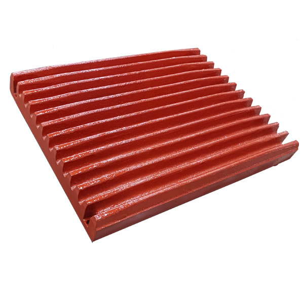
Jaw Plate
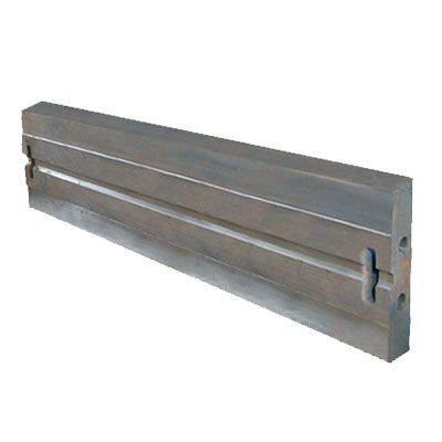
Blow Bar
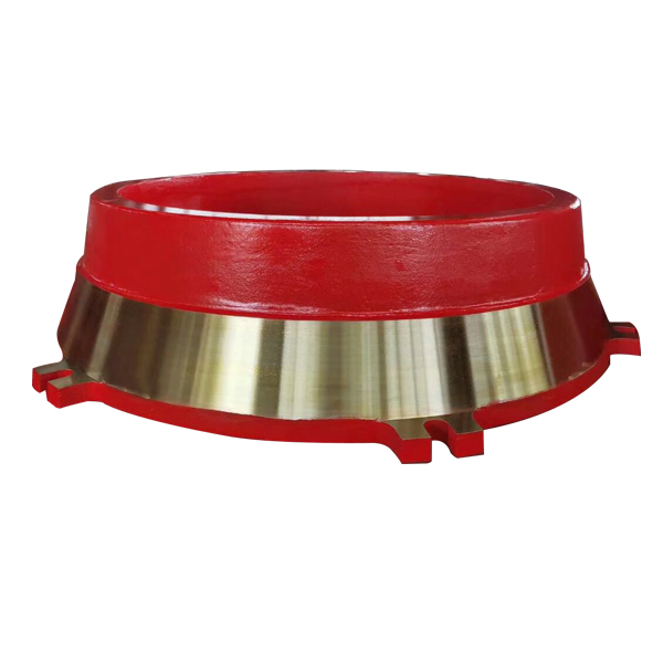
Mantle & Concave
Grate Bar
Contact Us
Get a quote within 24 hours. Send us your inquiry today.

+86 199 8785 7268
Mon-Sat 8AM-10PM CST Scan to chat — English, Spanish, Chinese Send photos of worn parts for instant quote

+86 199 8785 7268
Scan to follow — factory updates and quotes Chat in Chinese or English